
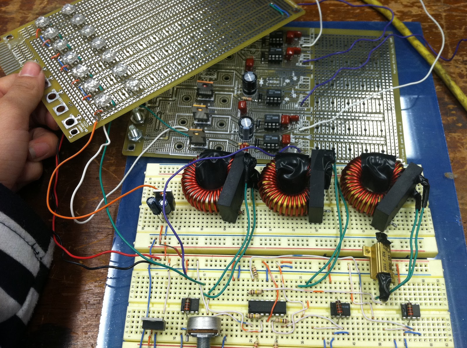
Here's what I've got so far - a mess of wires (soon to be sorted), and 3 sliding 10K potentiometers on the left that control the red, green, and blue color values. For the background soundtrack, you can listen to the two Jordan's at MITERS (the female of whom has an awesome blog: [T3CHNOLOCHIC]) discuss 'hella Bohemian (?)' for some reason:
(Apologies for shaky one-handed iPhone recording!)
Above: Video of RGBeta testing.
Arduino's are awesome (haha)! I write a bit of code, upload it to the Arduino, connect it to some LEDs and potentiometers... and things magically work! Plus, what's cool is that this little Arduino can do all the PWM magic digitally that I had to do analog-ly before for my class. Here was the first thing I made using it:

Above: Yay single RGB LED! Making it fade using an Arduino Nano.
In the above photo, I'm actually using a leftover Piranha LED that I bought for class, shipped from the UK. These little RGB LEDs gave me more trouble than expected, as the supplier website didn't have a datasheet, and after testing them I found that the LEDs were common ANODE [+] (whereas my design was tailored to common CATHODE [-]). Here are some surviving photos of my RGB lightbox, ALPHA version:
Above: It uses 3 buck converters, and (in this photo) is missing
2 power resistors and 2 potentiometers. The lightboard stacks on top.

Above: RGB lightbox Alpha testing. Sadly doesn't work quite as well,
and (in this photo) I've already blown a piranha LED just testing the first row, haha.
Comparing with what I have now, RGBeta is not as impressive looking as RGB Alpha, which had 3 legit-looking inductors and power resistors, as well as a separate board complete with 3 H-bridges (only lowsides used). But RGBeta is definitely cleaner and lighter, as well as less painful to make and debug. In fact, the only major debugging issue I ran into was because I forgot to make a common ground (my most common mistake), which ended up creating a flickering unstable light that semi-responded to the potentiometer slides. Grounding issues aside, RGBeta was definitely much easier to create.

Above: RGBeta is definitely more boss that RGB Alpha.
Side note: I've been unknowingly shortening my current 'RGB lightbox' to 'RGBeta' (pronounced R - G - Beta), since I consider this version the Beta version (the Alpha one being the one I made for class). Though, 'Beta' is probably not the right term to use, since this isn't a software release. What's more, every time I say it, it reminds me of RGVeda, the debut manga of CLAMP, and RigVeda [wiki], a sacred text of Hinduism - even though my lightbox is completely unrelated, haha. :)
Why do I want a lightbox? I confess, I'm biased as an artist and I'll mainly be using it to ink over sketches and learn animation. However, because it'll be a portable desk, the uses for it are limitless. (If I add a detachable cushion-y underside to the lightbox, I could set my laptop on top and have a comfy laptop lap desk, too! :D ). I discovered another use when Bailey ([ISOPACK]) was using a light to match up 2 printed circuit designs (for the top and bottom layer of the double-sided copper clad), in preparation for etching.


Above: Bailey's printed designs, in prep for DIY etching a printed circuit board.
I just need to solder on some more LED strips, provide a portable power supply, transfer circuit from breadboard to PCB (or other), design the frame and then build it!

Above: An approach we used to block out a scene in Killian Court,
using spools as cast members. Later, one of the directors even made a
mini model of the set so we could visualize the space.
It sounds like this program could help anyone that just needs a quick way to explain a series of positions - dance formations, chess/checkers/go/board game strategies, WWII troop movements for history presentations, sports play strategies, film/book/comic storyboarding, re-creation of events, etc. This idea already ended up on the list of things I wanted to make, so let's hope I get to it soon!
:) happy Birthday LUUUUUUUUUU
ReplyDelete